
Page 117 - Dynamics and Control of Nuclear Reactors
P. 117
112 CHAPTER 10 Reactor thermal-hydraulics
where
M f ¼ mass of fuel
C f ¼ specific heat capacity of fuel
T f ¼fuel temperature
P f ¼power released in the fuel node
U¼overall fuel-to-coolant heat transfer coefficient
A¼fuel cylinder surface area (fuel-to-coolant heat transfer area)
θ avg ¼average coolant temperature in the adjacent coolant node
Eq. (10.1) may be rewritten as
dT f UA P f
¼ T f θ avg + (10.2)
dt M f C f M f C f
The quantity, (M f C f /UA) has the units of time. It is the time constant for fuel-to-
coolant heat transfer. Typical values for LWRs and CANDU reactors are 4 to 5s.
10.3 Heat transfer to liquid coolant
The core heat transfer model also requires heat balance equations for the coolant. A
general model requires mass and energy balances. If the coolant density and node
volume are constant, a mass balance is not needed (see Section 10.4 for a discussion
of heat transfer in a model with a moving boundary).
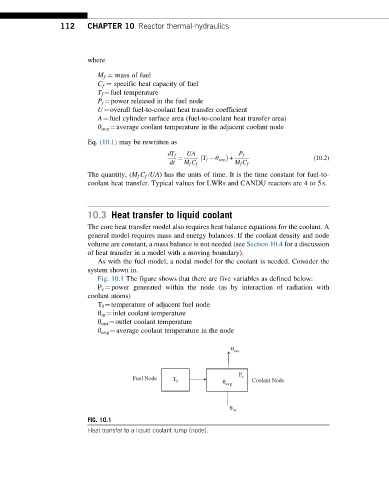
As with the fuel model, a nodal model for the coolant is needed. Consider the
system shown in.
Fig. 10.1 The figure shows that there are five variables as defined below:
P c ¼power generated within the node (as by interaction of radiation with
coolant atoms)
T f ¼temperature of adjacent fuel node
θ in ¼inlet coolant temperature
θ out ¼outlet coolant temperature
θ avg ¼average coolant temperature in the node
θ out
P
Fuel Node T f θ avg c Coolant Node
θ in
FIG. 10.1
Heat transfer to a liquid coolant lump (node).