
Page 119 - Dynamics and Control of Nuclear Reactors
P. 119
114 CHAPTER 10 Reactor thermal-hydraulics
where
M c ¼mass of coolant in a node
C c ¼specific heat capacity of coolant
θ 1 ¼temperature in the first coolant node
θ 2 ¼temperature in the second coolant node
W¼coolant mass flow rate
U¼overall heat transfer coefficient from fuel to coolant
A¼total fuel surface area for fuel to coolant heat transfer
P c1 ¼heat generation rate in the first coolant node
P c2 ¼heat generation rate in the second coolant node.
Note that the fuel-to-coolant heat transfer is given by the difference between the fuel
temperature and the temperature of the first coolant node (assumed equal to the outlet
temperature of that coolant node). The fuel-to-coolant heat transfer is divided equally
to both coolant nodes in this formulation.
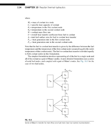
The simplest formulation involves representing all of the fuel in a single node and
all of the coolant as a pair of Mann’s nodes. A more detailed formulation uses a series
of axial fuel nodes, each coupled with a pair of Mann’s nodes. See Fig. 10.3 for the
case of two fuel nodes.
∼ ∼
Θ 4 = Θ out
∼
Θ 4
∼
T f2 Θ 3
∼
Θ 3
∼
Θ 2
∼
Θ 2
∼
T f1 Θ 1
∼
Θ 1
∼
Θ in
FIG. 10.3
Series of Mann’s models for more than one fuel node (two fuel nodes) representation.