
Page 118 - Dynamics and Control of Nuclear Reactors
P. 118
10.3 Heat transfer to liquid coolant 113
The nodal internal power generation, P c , the fuel temperature, T f , and the inlet
coolant temperature, θ in , are defined by other subsystem equations. That leaves
two variables, but the coolant equation provides only one. An assumption is required
to eliminate θ out . θ avg must be retained because it appears in the equation for heat
transfer from fuel to coolant. The average temperature is given by the following:
θ avg ¼ θ in + θ out Þ=2 (10.3)
ð
or
(10.4)
θ out ¼ 2 θ avg θ in
There is a problem with this formulation. Note in Eq. (10.4) that a sudden increase in
inlet temperature would cause a sudden decrease in outlet temperature. This is an
unphysical feature, causing consideration of an alternate formulation.
Another possibility is the “well-stirred-tank” formulation. That is, the outlet tem-
perature from the node is set equal to the average node temperature. This solves the
problem in the previous formulation, but equating average and outlet temperatures
does not represent actual behavior very well.
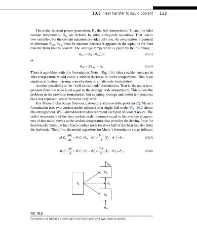
Ray Mann of Oak Ridge National Laboratory addressed the problem [2]. Mann’s
formulation uses two coolant nodes adjacent to a single fuel node; Fig. 10.2 shows
this arrangement. Well-stirred-tank models represent each pair of coolant nodes. The
outlet temperature of the first coolant node (assumed equal to the average tempera-
ture of that node) serves as the coolant temperature that provides the driving force for
heat transfer from the fuel. Each coolant node receives half of the heat transfer from
the fuel node. Therefore, the model equations for Mann’s formulation are as follows:
dθ 1 UA
ð
M c C c ¼ WC c θ in θ 1 Þ + T f θ 1 + P c1 (10.5)
dt 2
dθ 2 UA
ð
M c C c ¼ WC c θ 1 θ 2 Þ + T f θ 1 + P c2 (10.6)
dt 2
∼
Θ 2
∼
Θ 2
∼
T f Θ 1
∼
Θ 1
Q in
FIG. 10.2
Schematic of Mann’s model with one fuel node and two coolant nodes.