
Page 150 - Dynamics of Mechanical Systems
P. 150
0593_C05_fm Page 131 Monday, May 6, 2002 2:15 PM
Planar Motion of Rigid Bodies — Methods of Analysis 131
and
a = a + αα × r + ωω ×(ωω × r) (5.3.11)
Q
P
Example 5.3.1: Motion of a Piston, Connecting Rod, Crank Arm
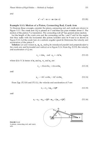
To illustrate these concepts, consider the piston, connecting rod, and crank arm shown in
Figure 5.3.3. The crank arm OQ is pinned at O and thus has pure rotation about O. The
motion of the piston P is translation. The connecting rod QP has general plane motion.
Let the length of the crank arm and the connecting rod be r and and let the angles
that they make with the horizontal (the piston/cylinder axis) be θ and φ as shown in
Figure 5.3.3. Let the crank turn at a uniform angular speed Ω. Determine the velocity and
acceleration of the piston P.
Solution: Let unit vectors n , n , n , and n be introduced parallel and perpendicular to
θ
r
x
y
the crank arm and horizontal and vertical as in Figure 5.3.4. From Eq. (5.3.9), the velocity
and acceleration of Q are:
v = rΩ n and a = − rΩ 2 n (5.3.12)
Q θ Q r
θ
˙
where Ω is . In terms of n and n , v and a are:
x
Q
Q
y
v = rΩsinθ n + rΩcosθ n (5.3.13)
Q x y
and
a =− rΩ cosθ n − rΩ sinθ n (5.3.14)
2
2
Q x y
From Eqs. (5.3.10) and (5.3.11), the velocity and acceleration of P are:
v = v + ωω × QP (5.3.15)
P Q QP
and
×
a = a + αα × QP + ωω QP ( ωω × QP) (5.3.16)
P Q QP QP
Q
r
θ
O φ
P
FIGURE 5.3.3
A piston, connecting rod, and crank
arm.