Page 155 - Dynamics of Mechanical Systems
P. 155

0593_C05_fm  Page 136  Monday, May 6, 2002  2:15 PM


                       136                                                 Dynamics of Mechanical Systems


                           v  P                   B                   v  P                   B
                                          v  Q                                       v  Q

                            P             Q                            P             Q             O

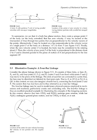
                       FIGURE 5.4.5                               FIGURE 5.4.6
                       A body  B with particles P  and Q  having parallel  Location of the center of zero velocity for a body
                       velocities with non-equal magnitudes.      having distinct particles with parallel but unequal
                                                                  velocities.
                        To summarize, we see that if a body has planar motion, there exists a unique point O
                       of the body (or the body extended) that has zero velocity. O  may be located at the
                       intersection of lines through two points that are perpendicular to the velocity vectors of
                       the points. Alternatively, O may be located on a line perpendicular to the velocity vector
                                                                  P
                       of a single point P of the body at a distance v /ω from P (see Figure 5.4.7). Finally,
                       when the zero velocity center O is located, the body may be considered to be rotating
                       about O. Then, the velocity of any point P of the body is proportional to the distance from
                       O to P and is directed parallel to the plane of motion of B and perpendicular to the line
                       segment OP.


                       5.5  Illustrative Example: A Four-Bar Linkage
                       Consider the planar linkage shown in Figure 5.5.1. It consists of three links, or bars (B ,
                                                                                                     1
                       B , and B ), and four joints (O, P, Q, and R). Joints O and R are fixed while joints P and Q
                        2
                               3
                       may move in the plane of the linkage. The ends of each bar are connected to a joint; thus,
                       the bars may be identified (or labeled) by their joint ends. That is, B  is OP, B  is PQ, B  is
                                                                                   1
                                                                                                   3
                                                                                           2
                       QR. In this context, we may also imagine a fourth bar B  connecting the fixed joints O and
                                                                        4
                       R. The system then has four bars and is thus referred to as a four-bar linkage.
                        The four-bar linkage may be used to model many physical systems employed in mech-
                       anisms and machines, particularly cranks and connecting rods. The four-bar linkage is
                       thus an excellent practical example for illustrating the concepts of the foregoing sections.
                       In this context, observe that bars  OP(B ) and  RQ(B ) undergo pure rotation, while bar
                                                          1
                                                                     3
                       PQ(B ) undergoes general plane motion, and bar OR(B ) is fixed, or at rest.
                                                                        4
                           2
                                    v  P
                                                B
                                                                                             Q
                                                                                    B  2
                              P                                              P
                                        P
                                       v
                                       |     | /  ω
                                                                                                B  3
                                                                          B  1
                                                                                                    R
                                                   O                     O
                       FIGURE 5.4.7                                      FIGURE 5.5.1
                       Location of the center for zero velocity knowing  A four-bar linkage.
                       the velocity of one particle and the angular
                       speed.
   150   151   152   153   154   155   156   157   158   159   160