
Page 158 - Dynamics of Mechanical Systems
P. 158
0593_C05_fm Page 139 Monday, May 6, 2002 2:15 PM
Planar Motion of Rigid Bodies — Methods of Analysis 139
Q 2 λ Q
B 2 n 2
45° y 45°
3.0 m
B 2 ν 3
P 30° B 3 P 30°
OP
OP
α = 4 rad/sec 2 4.95 m α = 4 rad/sec 2 λ 3
OP
OP
2.0 m ω = 5 rad/sec λ 1 ω = 5 rad/sec B 3 n x
B 1
ν 1 n z
O 6.098 m R O B 1 R
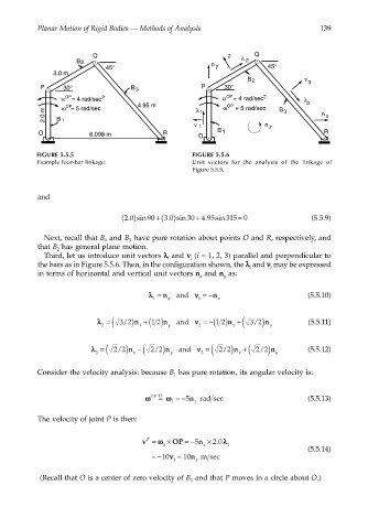
FIGURE 5.5.5 FIGURE 5.5.6
Example four-bar linkage. Unit vectors for the analysis of the linkage of
Figure 5.5.5.
and
. ( )
+
=
2 0 sin 90 +( ) 30 4 95sin 315 0 (5.5.9)
.
3 0 sin
.
Next, recall that B and B have pure rotation about points O and R, respectively, and
3
1
that B has general plane motion.
2
Third, let us introduce unit vectors λλ λλ and νν νν (i = 1, 2, 3) parallel and perpendicular to
i
i
the bars as in Figure 5.5.6. Then, in the configuration shown, the λλ λλ and νν νν may be expressed
i
i
in terms of horizontal and vertical unit vectors n and n as:
x
y
λλ = n and νν = −n (5.5.10)
1 y 1 x
λλ = ( +( νν =−( +(
/
/
2 3 2)n x 12)n and 2 12)n x 3 2)n y (5.5.11)
y
λλ = ( −( νν = ( +(
/
/
/
/
3 22)n x 22)n and 3 22)n x 22)n y (5.5.12)
y
Consider the velocity analysis: because B has pure rotation, its angular velocity is:
1
=
ωω OP D ωω =−5n z rad sec (5.5.13)
1
The velocity of joint P is then:
v = ωω × OP = −5 n × 2 0 λλ
P
.
1 z 1
(5.5.14)
=−10 νν = 10 n m sec
1 x
(Recall that O is a center of zero velocity of B and that P moves in a circle about O.)
1