
Page 162 - Dynamics of Mechanical Systems
P. 162
0593_C05_fm Page 143 Monday, May 6, 2002 2:15 PM
Planar Motion of Rigid Bodies — Methods of Analysis 143
O X O X
θ 1 β 1 β 2
θ β
2 3
θ 3
β
N
θ
N-1
θ
N
Z Z
FIGURE 5.6.1 FIGURE 5.6.2
A chain of N bars. Relative orientation angles.
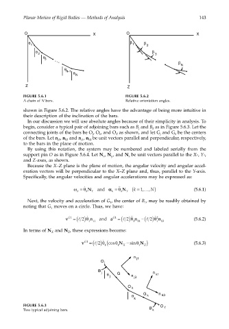
shown in Figure 5.6.2. The relative angles have the advantage of being more intuitive in
their description of the inclination of the bars.
In our discussion we will use absolute angles because of their simplicity in analysis. To
begin, consider a typical pair of adjoining bars such as B and B as in Figure 5.6.3. Let the
k
j
connecting joints of the bars be O , O , and O as shown, and let G and G be the centers
j
k
k
j
of the bars. Let n , n and n , n be unit vectors parallel and perpendicular, respectively,
k1
k3
j1
j3
to the bars in the plane of motion.
By using this notation, the system may be numbered and labeled serially from the
support pin O as in Figure 5.6.4. Let N , N , and N be unit vectors parallel to the X-, Y-,
x
z
y
and Z-axes, as shown.
Because the X–Z plane is the plane of motion, the angular velocity and angular accel-
eration vectors will be perpendicular to the X–Z plane and, thus, parallel to the Y-axis.
Specifically, the angular velocities and angular accelerations may be expressed as:
ω = θ N and αα k = ˙˙ k Y ( k = …, N) (5.6.1)
˙
,
θ N
1
k
k
Y
Next, the velocity and acceleration of G , the center of B , may be readily obtained by
1
1
noting that G moves on a circle. Thus, we have:
1
˙˙
v G1 = (l 2)θ ˙ n and a G1 = (l 2)θ n −(l 2)θ 2 ˙ n (5.6.2)
111 111 1 13
In terms of N and N , these expressions become:
X
Z
v G1 = (l 2)θ ˙ 1 (cosθ 1 N − sinθ 1 N ) (5.6.3)
Z
X
n
j1
O j
B
j n
θ G k1
j n j3
O
k
θ G k n k3
k
FIGURE 5.6.3 O
Two typical adjoining bars. B k