
Page 151 - Dynamics of Mechanical Systems
P. 151
0593_C05_fm Page 132 Monday, May 6, 2002 2:15 PM
132 Dynamics of Mechanical Systems
n
y
n r n
n θ z
Q
r
θ φ
O P n
x x
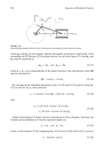
FIGURE 5.3.4
Geometrical parameters and unit vectors of the piston, connecting rod, and crank arm system.
where ωω ωω and αα αα are the angular velocity and angular acceleration, respectively, of the
QP
QP
connecting rod QP. Because QP has planar motion, we see from Figure 5.3.4 that ωω ωω and
QP
αα α α may be expressed as:
QP
˙˙
ωω =−φn and αα =−φn (5.3.17)
˙
QP z QP z
where n (= n × n ) is perpendicular to the plane of motion. Also, the position vector QP
x
y
z
may be expressed as:
QP = lcosφ n − lsinφ n y (5.3.18)
x
By carrying out the indicated operations of Eqs. (5.3.15) and (5.3.16) and by using Eqs.
(5.3.13) and (5.3.14), v and a become:
P
P
v =− ( rΩsinθ − φ ˙ sin n ) φ x ( rΩcosθ − φ ˙ cos n ) y (5.3.19)
+
l
l
P
and
a =− ( rΩ cosθ − φ sinφ − φ 2 ˙ n ) φ
˙˙
2
l
l
P cos x (5.3.20)
r (
˙˙
+− Ω sinθ − φ cosφ + φ 2 ˙ sin n ) φ
2
l
l
y
Observe from Figure 5.3.4 that P moves in translation in the n direction. Therefore, the
x
velocity and acceleration of P may be expressed simply as:
v = ˙ x n and a = ˙˙ n (5.3.21)
x
P x P x
where x is the distance OP. By comparing Eqs. (5.3.19) and (5.3.20) with (5.3.21), we have:
˙ x =− rΩ sin − φ ˙ sinφ (5.3.22)
θ
l