
Page 197 - Dynamics of Mechanical Systems
P. 197
0593_C06_fm Page 178 Monday, May 6, 2002 2:28 PM
178 Dynamics of Mechanical Systems
F F
F F
+ δ
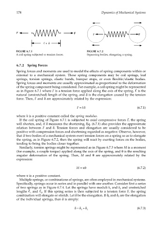
FIGURE 6.7.1 FIGURE 6.7.2
A coil spring subjected to tension forces. Separating bodies, elongating a spring.
6.7.2 Spring Forces
Spring forces and moments are used to model the effects of spring components within or
external to a mechanical system. These spring components may be coil springs, leaf
springs, torsion springs, elastic bands, bumper stops, or even flexible/elastic bodies.
Spring forces and moments are usually approximated as proportional to the deformation
of the spring component being considered. For example, a coil spring might be represented
as in Figure 6.7.1 where F is a tension force applied along the axis of the spring, is the
natural (unstretched) length of the spring, and δ is the elongation caused by the tension
force. Then, F and δ are approximately related by the expression:
F =δ (6.7.1)
k
where k is a positive constant called the spring modulus.
If the coil spring of Figure 6.7.1 is subjected to axial compressive forces F, the spring
will shorten, and, if δ measures the shortening, Eq. (6.7.1) also provides the approximate
relation between F and δ. Tension forces and elongation are usually considered to be
positive with compression forces and shortening regarded as negative. Observe, however,
that if two bodies of a mechanical system exert tension forces on a spring so as to elongate
the spring, as in Figure 6.7.2, then the spring will react by exerting forces on the bodies,
tending to bring the bodies closer together.
Similarly, torsion springs might be represented as in Figure 6.7.3 where M is a moment
(for example, a couple torque) applied along the axis of the spring, and θ is the resulting
angular deformation of the spring. Then, M and θ are approximately related by the
expression:
M =κθ (6.7.2)
where κ is a positive constant.
Multiple springs, or combinations of springs, are often employed in mechanical systems.
Specifically, springs occur in series and in parallel with one another. Consider first a series
of two springs as in Figure 6.7.4. Let the springs have moduli k and k and unstretched
2
1
lengths and . If this spring series is then subjected to a tension force F, the spring
2
1
combination will elongate or stretch. Let δ be the elongation. If δ and δ are the elongation
1
2
of the individual springs, then δ is simply:
δ = δ + δ (6.7.3)
1 2