
Page 242 - Dynamics of Mechanical Systems
P. 242
0593_C07_fm Page 223 Monday, May 6, 2002 2:42 PM
Inertia, Second Moment Vectors, Moments and Products of Inertia, Inertia Dyadics 223
n
n b
2
θ
n
1
FIGURE 7.9.2
Unit vectors parallel to a plane of θ
symmetry. n a
I + I
aa bb
2 I 11
I I bb I 2 I aa
12 22
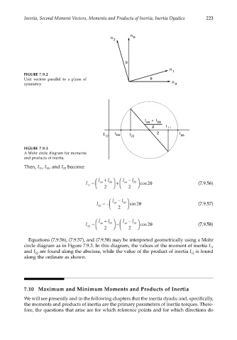
FIGURE 7.9.3
A Mohr circle diagram for moments
and products of inertia.
Then, I , I , and I become:
22
11
12
I + I I − I
I = aa bb + aa bb cos 2θ (7.9.56)
11 2 2
I − I
I =− aa bb sin 2θ (7.9.57)
12 2
I + I I − I
I = aa bb − aa bb cos 2θ (7.9.58)
22 2 2
Equations (7.9.56), (7.9.57), and (7.9.58) may be interpreted geometrically using a Mohr
circle diagram as in Figure 7.9.3. In this diagram, the values of the moment of inertia I 11
and I are found along the abscissa, while the value of the product of inertia I is found
12
22
along the ordinate as shown.
7.10 Maximum and Minimum Moments and Products of Inertia
We will see presently and in the following chapters that the inertia dyadic and, specifically,
the moments and products of inertia are the primary parameters of inertia torques. There-
fore, the questions that arise are for which reference points and for which directions do