
Page 439 - Dynamics of Mechanical Systems
P. 439
0593_C12_fm Page 420 Monday, May 6, 2002 3:11 PM
420 Dynamics of Mechanical Systems
and
( 12) cos θ 2 ( − θ 1) θ ˙˙ 1 +( 13) θ 2 −( 12)θ 2 ˙ 1 sin 1 (θ − θ 2) +(g 2 ) sinθ 2 = 0 (12.2.23)
˙˙
l
Equations (12.2.22) and (12.2.23) are identical to Eqs. (8.10.12) and (8.10.13) obtained
using d’Alembert’s principle. By reviewing the analysis of Section 8.10, we see that the
final form of the governing equations is obtained more directly (that is, without subsequent
simplification) using Kane’s equations.
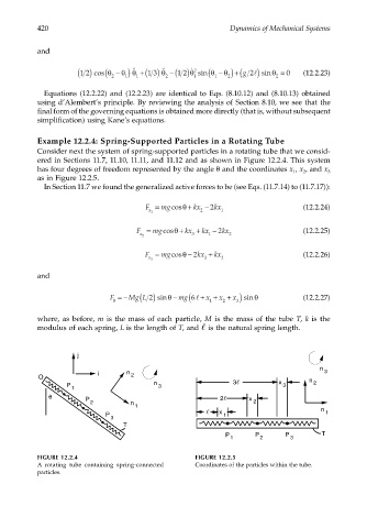
Example 12.2.4: Spring-Supported Particles in a Rotating Tube
Consider next the system of spring-supported particles in a rotating tube that we consid-
ered in Sections 11.7, 11.10, 11.11, and 11.12 and as shown in Figure 12.2.4. This system
has four degrees of freedom represented by the angle θ and the coordinates x , x , and x 3
2
1
as in Figure 12.2.5.
In Section 11.7 we found the generalized active forces to be (see Eqs. (11.7.14) to (11.7.17)):
F = mgcosθ + kx − 2 kx (12.2.24)
x 1 2 1
F = mgcosθ + kx + kx − 2 kx (12.2.25)
x 2 3 1 2
F = mgcosθ − 2 kx + kx (12.2.26)
x 3 3 2
and
F =− Mg L ( ) 2 sin θ − mg(6l + x + x + ) sin θ (12.2.27)
x
θ
2
1
3
where, as before, m is the mass of each particle, M is the mass of the tube T, k is the
modulus of each spring, L is the length of T, and is the natural spring length.
j
n 3
i n 2
O n
P n 3 3 x 3 2
1
θ
P 2 x
2 n 2
1 n
P x 1 1
3
T
P P P T
1 2 3
FIGURE 12.2.4 FIGURE 12.2.5
A rotating tube containing spring-connected Coordinates of the particles within the tube.
particles.