
Page 491 - Dynamics of Mechanical Systems
P. 491
0593_C13_fm Page 472 Monday, May 6, 2002 3:21 PM
472 Dynamics of Mechanical Systems
c
B
k
m
F(t)
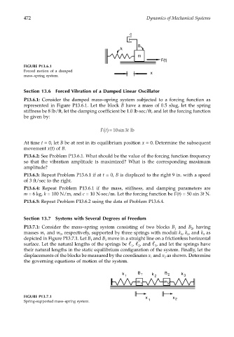
FIGURE P13.6.1
Forced motion of a damped x
mass–spring system.
Section 13.6 Forced Vibration of a Damped Linear Oscillator
P13.6.1: Consider the damped mass–spring system subjected to a forcing function as
represented in Figure P13.6.1. Let the block B have a mass of 0.5 slug, let the spring
stiffness be 8 lb/ft, let the damping coefficient be 1.0 lb⋅sec/ft, and let the forcing function
be given by:
Ft () = 10sin t 3 lb
At time t = 0, let B be at rest in its equilibrium position x = 0. Determine the subsequent
movement x(t) of B.
P13.6.2: See Problem P13.6.1. What should be the value of the forcing function frequency
so that the vibration amplitude is maximized? What is the corresponding maximum
amplitude?
P13.6.3: Repeat Problem P13.6.1 if at t = 0, B is displaced to the right 9 in. with a speed
of 3 ft/sec to the right.
P13.6.4: Repeat Problem P13.6.1 if the mass, stiffness, and damping parameters are
m = 6 kg, k = 100 N/m, and c = 10 N⋅sec/m. Let the forcing function be F(t) = 50 sin 3t N.
P13.6.5: Repeat Problem P13.6.2 using the data of Problem P13.6.4.
Section 13.7 Systems with Several Degrees of Freedom
P13.7.1: Consider the mass–spring system consisting of two blocks B and B , having
1
2
masses m and m , respectively, supported by three springs with moduli k , k , and k as
3
1
2
2
1
depicted in Figure P13.7.1. Let B and B move in a straight line on a frictionless horizontal
2
1
surface. Let the natural lengths of the springs be , , and , and let the springs have
3
2
1
their natural lengths in the static equilibrium configuration of the system. Finally, let the
displacements of the blocks be measured by the coordinates x and x as shown. Determine
2
1
the governing equations of motion of the system.
k B 1 k B 2 k
1 2 3
m 1 m 2
FIGURE P13.7.1 x x 2
Spring-supported mass–spring system. 1