
Page 504 - Dynamics of Mechanical Systems
P. 504
0593_C14_fm Page 485 Tuesday, May 7, 2002 6:56 AM
Stability 485
2
(specifically, Ω < g/r), there are only two equilibrium positions: θ = θ = 0 and θ = θ = π,
1
2
with θ = θ = 0 being stable (see Eq. (14.3.7)) and θ = θ = π being unstable (see Eq. (14.3.10)).
1
2
2
For fast tube rotation (specifically, Ω > g/r), there are three equilibrium positions:
2
–1
θ = θ = 0, θ = θ = π, and θ = θ = cos (g/rΩ ), with θ = θ = 0 and θ = θ = π being unstable
2
1
3
1
2
(see Eqs. (14.3.7) and (14.3.10)) and θ = θ = cos (g/rΩ ) being stable (see Eq. (14.3.16)).
–1
2
3
That is, the third equilibrium position does not exist unless the tube rotation is such that
2
Ω > g/r, but if it does exist, it is stable.
14.4 A Freely Rotating Body
Consider next an arbitrarily shaped body B that is thrown into the air, rotating about one
of its central principal axes of inertia. Our objective is to explore the stability of that motion;
that is, will the body continue to rotate about the principal inertia axis or will it be unstable,
wobbling away from the axis?
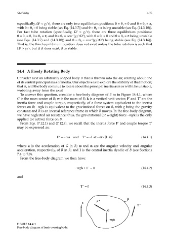
To answer this question, consider a free-body diagram of B as in Figure 14.4.1, where
G is the mass center of B; m is the mass of B; k is a vertical unit vector; F and T are the
*
*
inertia force and couple torque, respectively, of a force system equivalent to the inertia
forces on B; –mgk is equivalent to the gravitational forces on B, with g being the gravity
constant; and R is an inertial reference frame in which B moves. In the free-body diagram,
we have neglected air resistance; thus, the gravitational (or weight) force –mgk is the only
applied (or active) force on B.
From Eqs. (7.12.1) and (7.12.8), we recall that the inertia force F and couple torque T *
*
may be expressed as:
I⋅ )
α
F =−m a and T =− ⋅ −αωω × ( ωω (14.4.1)
I
*
*
where a is the acceleration of G in R; ωω ωω and αα αα are the angular velocity and angular
acceleration, respectively, of B in R; and I is the central inertia dyadic of B (see Sections
7.4 to 7.9).
From the free-body diagram we then have:
+
−mgkF * = 0 (14.4.2)
and
T = 0 (14.4.3)
*
B
F *
k
T *
G
-mgk
FIGURE 14.4.1
Free-body diagram of freely rotating body.