
Page 187 - Electric Drives and Electromechanical Systems
P. 187
Chapter 6 Brushless motors 181
where k is a constant which is introduced to accommodate the physical construction of
the stator windings, and B m is the air-gap flux density. The torque equation can also be
expressed in the form;
pE p I sin b
T ¼ (6.30)
u s
and hence,
u m T ¼ 3E p I sin b (6.31)
This verifies that the product of the back emf and the phase current is equal to the
input power at b ¼ p/2; therefore, the ability to control this angle is considered to be
critical to the satisfactory performance of the motor.
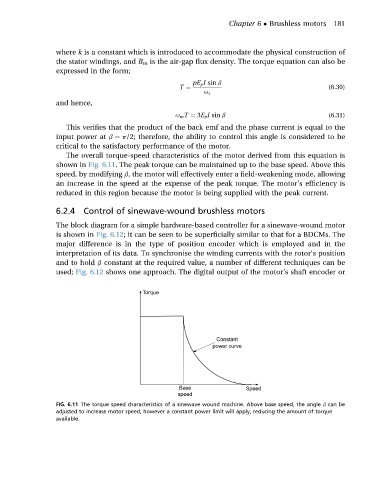
The overall torque-speed characteristics of the motor derived from this equation is
shown in Fig. 6.11. The peak torque can be maintained up to the base speed. Above this
speed, by modifying b, the motor will effectively enter a field-weakening mode, allowing
an increase in the speed at the expense of the peak torque. The motor’s efficiency is
reduced in this region because the motor is being supplied with the peak current.
6.2.4 Control of sinewave-wound brushless motors
The block diagram for a simple hardware-based controller for a sinewave-wound motor
is shown in Fig. 6.12; it can be seen to be superficially similar to that for a BDCMs. The
major difference is in the type of position encoder which is employed and in the
interpretation of its data. To synchronise the winding currents with the rotor’s position
and to hold b constant at the required value, a number of different techniques can be
used; Fig. 6.12 shows one approach. The digital output of the motor’s shaft encoder or
FIG. 6.11 The torque speed characteristics of a sinewave wound machine. Above base speed, the angle b can be
adjusted to increase motor speed, however a constant power limit will apply, reducing the amount of torque
available.