
Page 183 - Electric Drives and Electromechanical Systems
P. 183
Chapter 6 Brushless motors 177
6.1.6 Sensorless control
In order to reduce the cost and complexity of brushless d.c. motors it is possible to
remove the position sensors and rely on information obtained directly from the motor
to determine the commutation points. If the operation of the brushless d.c. motor, the
purpose of the sensors is to align the switching with the emf from the individual
phases. In a sensorless design, this is achieved by one of a number of approaches
including terminal voltage sensing, terminal current sensing, back-emf Integration
(Shao, 2006; Gamazo-Real et al., 2010).
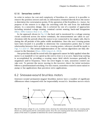
In the approach shown in Fig. 6.9 the back emf is monitored by a voltage sensing
circuit connected across the motor terminals, the measurements are taken in syn-
chronism with the periods when the motor is not connected to the supply rails, that is
during the off periods of the pulse width modulation. Once the zero crossing points
have been located it is possible to determine the commutation points due to fixed
relationship between them and the zero crossing points, referance should be made to
Figs. 6.4 and 6.5. The actual implementation of the various algorithms are fully dis-
cussed in the literature (Shao, 2006; Jung et al., 2014).
One point that should be noted with this approach cannot be fully applied when the
motor is at standstill or low speed as the emf is close to or at zero. Open-loop starting
is accomplished by providing a rotating stator field which increases gradually in
magnitude and/or frequency. Once the rotor begins to turn, sensorless control can
take over. To prevent the motor moving in the incorrect direct the initial excitation
follows a predetermined switching. For this reason, sensorless control is more suited to
pump or fan applications than precision servo applications.
6.2 Sinewave-wound brushless motors
Sinewave-wound permanent-magnet brushless motors have a number of significant
differences when compared with the trapezoidally wound d.c. brushless motors which
FIG. 6.9 The phase voltage for a d.c. brushless motor, showing the relationship between the zero crossing points
(shown as a solid square) and the commutation points. Once the zero crossing points have been detected on all
phases of the motor it is possible to determine the correct commutation points.