
Page 179 - Electric Drives and Electromechanical Systems
P. 179
Chapter 6 Brushless motors 173
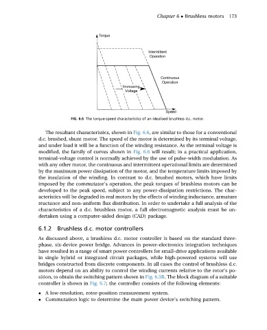
FIG. 6.6 The torque-speed characteristics of an idealised brushless d.c. motor.
The resultant characteristics, shown in Fig. 6.6, are similar to those for a conventional
d.c. brushed, shunt motor. The speed of the motor is determined by its terminal voltage,
and under load it will be a function of the winding resistance. As the terminal voltage is
modified, the family of curves shown in Fig. 6.6 will result; in a practical application,
terminal-voltage control is normally achieved by the use of pulse-width modulation. As
with any other motor, the continuous and intermittent operational limits are determined
by the maximum power dissipation of the motor, and the temperature limits imposed by
the insulation of the winding. In contrast to d.c. brushed motors, which have limits
imposed by the commutator’s operation, the peak torques of brushless motors can be
developed to the peak speed, subject to any power-dissipation restrictions. The char-
acteristics will be degraded in real motors by the effects of winding inductance, armature
reactance and non-uniform flux distribution. In order to undertake a full analysis of the
characteristics of a d.c. brushless motor, a full electromagnetic analysis must be un-
dertaken using a computer-aided design (CAD) package.
6.1.2 Brushless d.c. motor controllers
As discussed above, a brushless d.c. motor controller is based on the standard three-
phase, six-device power bridge. Advances in power-electronics integration techniques
have resulted in a range of smart power controllers for small-drive applications available
in single hybrid or integrated circuit packages, while high-powered systems will use
bridges constructed from discrete components. In all cases the control of brushless d.c.
motors depend on an ability to control the winding currents relative to the rotor’s po-
sition, to obtain the switching pattern shown in Fig. 6.5B. The block diagram of a suitable
controller is shown in Fig. 6.7; the controller consists of the following elements:
A low-resolution, rotor-position measurement system.
Commutation logic to determine the main power device’s switching pattern.