
Page 180 - Electric Drives and Electromechanical Systems
P. 180
174 Electric Drives and Electromechanical Systems
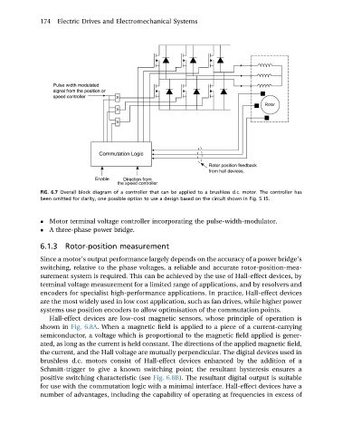
FIG. 6.7 Overall block diagram of a controller that can be applied to a brushless d.c. motor. The controller has
been omitted for clarity, one possible option to use a design based on the circuit shown in Fig. 5.15.
Motor terminal voltage controller incorporating the pulse-width-modulator.
A three-phase power bridge.
6.1.3 Rotor-position measurement
Since a motor’s output performance largely depends on the accuracy of a power bridge’s
switching, relative to the phase voltages, a reliable and accurate rotor-position-mea-
surement system is required. This can be achieved by the use of Hall-effect devices, by
terminal voltage measurement for a limited range of applications, and by resolvers and
encoders for specialist high-performance applications. In practice, Hall-effect devices
are the most widely used in low cost application, such as fan drives, while higher power
systems use position encoders to allow optimisation of the commutation points.
Hall-effect devices are low-cost magnetic sensors, whose principle of operation is
shown in Fig. 6.8A. When a magnetic field is applied to a piece of a current-carrying
semiconductor, a voltage which is proportional to the magnetic field applied is gener-
ated, as long as the current is held constant. The directions of the applied magnetic field,
the current, and the Hall voltage are mutually perpendicular. The digital devices used in
brushless d.c. motors consist of Hall-effect devices enhanced by the addition of a
Schmitt-trigger to give a known switching point; the resultant hysteresis ensures a
positive switching characteristic (see Fig. 6.8B). The resultant digital output is suitable
for use with the commutation logic with a minimal interface. Hall-effect devices have a
number of advantages, including the capability of operating at frequencies in excess of