
Page 181 - Electric Drives and Electromechanical Systems
P. 181
Chapter 6 Brushless motors 175
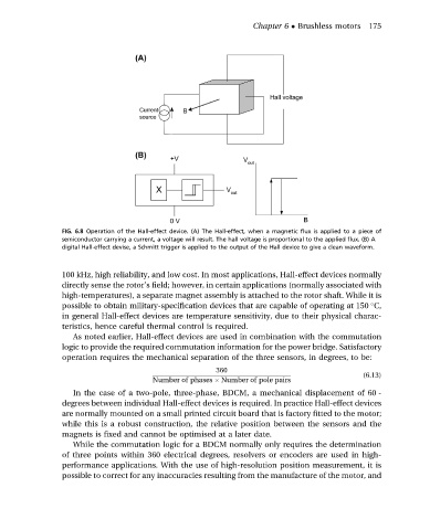
FIG. 6.8 Operation of the Hall-effect device. (A) The Hall-effect, when a magnetic flux is applied to a piece of
semiconductor carrying a current, a voltage will result. The hall voltage is proportional to the applied flux. (B) A
digital Hall-effect devise, a Schmitt trigger is applied to the output of the Hall device to give a clean waveform.
100 kHz, high reliability, and low cost. In most applications, Hall-effect devices normally
directly sense the rotor’s field; however, in certain applications (normally associated with
high-temperatures), a separate magnet assembly is attached to the rotor shaft. While it is
possible to obtain military-specification devices that are capable of operating at 150 C,
in general Hall-effect devices are temperature sensitivity, due to their physical charac-
teristics, hence careful thermal control is required.
As noted earlier, Hall-effect devices are used in combination with the commutation
logic to provide the required commutation information for the power bridge. Satisfactory
operation requires the mechanical separation of the three sensors, in degrees, to be:
360
(6.13)
Number of phases Number of pole pairs
In the case of a two-pole, three-phase, BDCM, a mechanical displacement of 60 -
degrees between individual Hall-effect devices is required. In practice Hall-effect devices
are normally mounted on a small printed circuit board that is factory fitted to the motor;
while this is a robust construction, the relative position between the sensors and the
magnets is fixed and cannot be optimised at a later date.
While the commutation logic for a BDCM normally only requires the determination
of three points within 360 electrical degrees, resolvers or encoders are used in high-
performance applications. With the use of high-resolution position measurement, it is
possible to correct for any inaccuracies resulting from the manufacture of the motor, and