
Page 175 - Electric Drives and Electromechanical Systems
P. 175
Chapter 6 Brushless motors 169
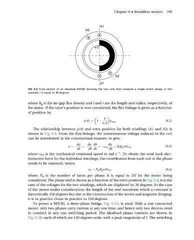
FIG. 6.3 Cross section of an idealised BDCM, showing the two coils that comprise a single motor phase, in this
example d is equal to 30 degrees.
where B g is the air-gap flux density and l and r are the length and radius, respectively, of
the stator. If the rotor’s position is now considered, the flux linkage is given as a function
of position by,
q
jðqÞ¼ 1 j max (6.2)
p=2
The relationship between j(q) and rotor position for both windings (A1 and A2) is
shown in Fig. 6.4. From the flux linkage, the instantaneous voltage induced in the coil
can be determined in the conventional manner, to give,
dj dj dq dj
e ¼ ¼ ¼ u m ¼ NB g prlu m (6.3)
dt dq dt dq
1
where u m is the mechanical rotational speed in rad s . To obtain the total back elec-
tromotive force for the individual windings, the contribution from each coil in the phase
needs to be summed; hence,
e p ¼ N p B g prlu m (6.4)
where N p is the number of turns per phase; it is equal to 2N for the motor being
considered. The phase emf is shown as a function of the rotor position in Fig. 6.4; it is the
sum of the voltages for the two windings, which are displaced by 30 degrees. In the case
of the motor under consideration; the length of the emf waveform which a constant is
theoretically 150 degrees but due to the construction of the motor and magnetic fringing,
it is in practice closer in practice to 120 degrees.
To power a BDCM, a three-phase bridge, Fig. 6.5A, is used. With a star connected
motor, only two phases carry current at any one time, and hence only two devices need
to conduct in any one switching period. The idealised phase currents are shown in
Fig. 6.5B; each of which are 120 degrees wide, with a peak magnitude of I. The switching