
Page 172 - Electric Drives and Electromechanical Systems
P. 172
166 Electric Drives and Electromechanical Systems
Sinewave-wound permanent-magnet synchronous motors incorporate windings
with an approximately sinusoidal distribution which are supplied with sinusoidal
currents. These motors are normally controlled by a version of vector control,
which has considerable similarities with the method used to control the asynchro-
nous induction motors discussed in Chapter 7, Induction Motors. To achieve the
required control resolution, these motors are fitted with a resolver or a similar
high-resolution position transducer as part of the control strategy.
Linear brushless motors based on conventional brushless technology, they make an
ideal replacement for high performance applications that would have been previ-
ously based on leadscrews and ballscrews.
As will be discussed, the operation of these permanent-magnet brushless motors is
totally dependent on their associated electronics, hence, as the reliability and availability
of power electronic devices and specialist integrated circuits has improved over the last
twenty years the number of applications has also increased. Due to these motors’ high
reliability and low-maintenance requirements, they are ideally suited to a wide range of
applications including computer cooling fans and robotic drives.
As with brushed motors, the brushless motor can be obtained in a number of
versions, not only in its electromagnetic characteristics as summarised above, but also in
its mechanical construction. The motors can be supplied either as a conventional framed
or a frameless motor, together with torque motor and printed circuit designs. The
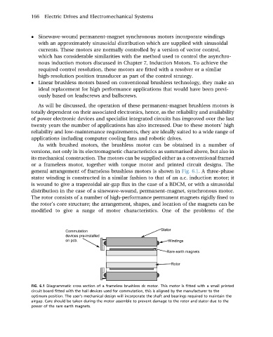
general arrangement of frameless brushless motors is shown in Fig. 6.1. A three-phase
stator winding is constructed in a similar fashion to that of an a.c. induction motor; it
is wound to give a trapezoidal air-gap flux in the case of a BDCM, or with a sinusoidal
distribution in the case of a sinewave-wound, permanent-magnet, synchronous motor.
The rotor consists of a number of high-performance permanent magnets rigidly fixed to
the rotor’s core structure; the arrangement, shapes, and location of the magnets can be
modified to give a range of motor characteristics. One of the problems of the
FIG. 6.1 Diagrammatic cross section of a frameless brushless dc motor. This motor is fitted with a small printed
circuit board fitted with the hall devices used for commutation, this is aligned by the manufacturer to the
optimum position. The user’s mechanical design will incorporate the shaft and bearings required to maintain the
airgap. Care should be taken during the motor assemble to prevent damage to the rotor and stator due to the
power of the rare earth magnets.