
Page 168 - Electric Drives and Electromechanical Systems
P. 168
Chapter 5 Brushed direct-current motors 161
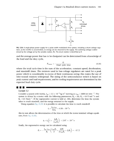
FIG. 5.20 A single-phase power supply for a pulse width modulated drive system, including a shunt voltage regu-
lator, as the rectifier is uncontrolled, no energy can be returned to the supply. The switching voltage is deter-
mined by the voltage set by the variable resistor, Rv. The shunt resistor is identified as R.
and the average power that has to be dissipated can be determined from a knowledge of
the load and the duty cycle,
E r
P resistor ¼ (5.33)
Total cycle time
where the total cycle time is the sum of the acceleration, constant speed, deceleration,
and standstill times. The resistors used in bus-voltage regulators are rated for a peak
power which is considerably in excess of their continuous rating; this makes the use of
wire-wound resistors widespread. The sizing of the semiconductor switch is based on
peak current and load requirements, and its cooling requirements are determined by the
expected load duty cycle.
nnn
Example 5.2
2
Consider a system with inertia, I tot ¼ 2.5 10 4 kg m running at u int ¼ 3000 rev min 1 . The
1
system is driven by a motor with the following parameters; R a ¼ 2U,K e ¼ 0.6 V rad s and
1
K t ¼ 0.6 NmA . If the regenerative current is held at -30A, determine the time the system
takes to reach standstill, and the energy returned to the supply.
Using equation Eq. (5.29) it is possible to calculate the time to reach standstill
I tot u int 3
t z ¼ ¼ 4:36 10 s
K t I R
this in turn allows the determination of the time at which the motor terminal voltage equals
zero, from Eq. (5.26).
I R R a 3
t 0 ¼ t z 1 þ ¼ 2:97 10 s
u int K e
finally, the regenerative energy can be calculated using
2 2
I tot u int u int K e I R a
R
E r ¼ þ þ I a R a ¼ 5:7 J
K t 2 2u int K e