
Page 163 - Electric Drives and Electromechanical Systems
P. 163
156 Electric Drives and Electromechanical Systems
proposed application of the drive. In addition to these devices, the power bridge will
include a current-sensing device for the current servo loop and device protection. As
with any power electronic system, the mechanical construction must be carefully
considered, particularly to ensure adequate heat dissipation, and a minimal lead length
to minimise switching transients.
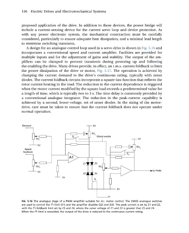
A design for an analogue control loop used in a servo drive is shown in Fig. 5.16 and
incorporates a conventional speed and current amplifier. Facilities are provided for
multiple inputs and for the adjustment of gains and stability. The output of the am-
plifiers can be clamped to prevent transients during powering up and following
the enabling the drive. Many drives provide, in effect, an r.m.s. current foldback to limit
the power dissipation of the drive or motor, Fig. 5.17. The operation is achieved by
clamping the current demand to the drive’s continuous rating, typically with zener
diodes. The current foldback circuits incorporate a square-law function that reflects the
rotor current heating in the load. The reduction in the current dependence is triggered
when the motor current modified by the square load exceeds a predetermined value for
a length of time, which is typically two to 3 s. The time delay is commonly provided by
aconventionalanalogueintegrator. Thereduction in the peak-current capability is
achievedbyasecond,lower-voltage,set of zener diodes. In the sizing of the motor-
drive, care must be taken to ensure that the current foldback does not operate under
normal operation.
FIG. 5.16 The analogue stage of a PWM amplifier suitable for d.c. motor control. The CMOS analogue switches
2
are used to control the I t limit (S1) and the amplifier disables (S2) and (S3). The peak current is set by Z1 and Z2,
2
with the I t foldback limit set by Z3 and Z4, where the zener voltage of Z1 and Z2 is greater that Z3 and Z4.
2
When the I t limit is exceeded, the output of the drive is reduced to the continuous current rating.