
Page 162 - Electric Drives and Electromechanical Systems
P. 162
Chapter 5 Brushed direct-current motors 155
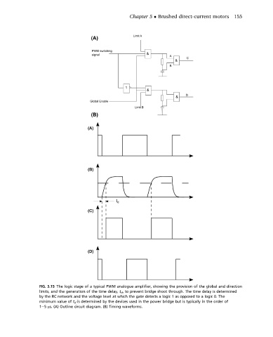
FIG. 5.15 The logic stage of a typical PWM analogue amplifier, showing the provision of the global and direction
limits, and the generation of the time delay, t d , to prevent bridge shoot through. The time delay is determined
by the RC network and the voltage level at which the gate detects a logic 1 as opposed to a logic 0. The
minimum value of t d is determined by the devices used in the power bridge but is typically in the order of
1e5 ms. (A) Outline circuit diagram. (B) Timing waveforms.