
Page 159 - Electric Drives and Electromechanical Systems
P. 159
152 Electric Drives and Electromechanical Systems
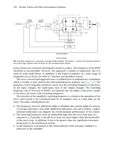
FIG. 5.12 Block diagram of a commercial analogue PWM amplifier. The blocks, L, contain the required protection
and control logic together with the drives for the individual power devices.
power devices are switched, allowing the current to reduce. The frequency of the PWM
waveform is uncontrolled. However, this approach is simple to implement, and it is
used on some small drives. In addition, it has found acceptance in a wide range of
integrated circuit drives, for both d.c. brushed and brushless motors.
The more conventional approach uses a modified form of subharmonic modulation
which is similar to that used by the telecommunications industry (see Fig. 5.14). The
frequency of the triangular-waveform carrier sets the switching frequency of the drive.
As the input changes, the mark/space ratio of the output changes. The switching
frequency can be in excess of 40 kHz. As a general rule, the higher is the power output
of the drive, the lower is the switching frequency.
The selection of the amplifier’s switching frequency is critical to the operation of the
drive, and it needs to be considered both by its designers and, at a later date, by the
users. The main considerations are:
The frequency must be sufficiently high to minimise the current ripple for motors
of average inductance and while additional inductance can and is added, a higher
armature inductance can degrade the overall dynamic performance of the system.
The switching frequency must be sufficiently high that the servo loop does not
respond to it. Typically, it should be at least ten times higher than the bandwidth
of the servo loop. In addition, it has to be greater than any significant resonance
frequencies in the mechanical system.
As the frequency is increased so the semiconductor losses increase, leading to a
reduction in the reliability.