
Page 155 - Electric Drives and Electromechanical Systems
P. 155
148 Electric Drives and Electromechanical Systems
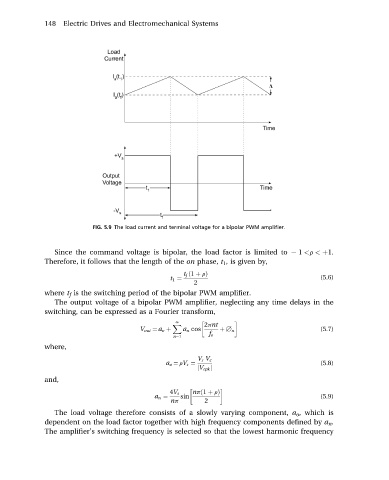
FIG. 5.9 The load current and terminal voltage for a bipolar PWM amplifier.
Since the command voltage is bipolar, the load factor is limited to 1 <r < þ1.
Therefore, it follows that the length of the on phase, t 1 , is given by,
t f ð1 þ rÞ
t 1 ¼ (5.6)
2
where t f is the switching period of the bipolar PWM amplifier.
The output voltage of a bipolar PWM amplifier, neglecting any time delays in the
switching, can be expressed as a Fourier transform,
N
X 2pnt
V out ¼ a o þ a n cos þ B n (5.7)
f e
n¼1
where,
V s V c
a o ¼ rV s ¼ (5.8)
jV cpk j
and,
4V s npð1 þ rÞ
a n ¼ sin (5.9)
np 2
The load voltage therefore consists of a slowly varying component, a o , which is
dependent on the load factor together with high frequency components defined by a n .
The amplifier’s switching frequency is selected so that the lowest harmonic frequency