
Page 156 - Electric Drives and Electromechanical Systems
P. 156
Chapter 5 Brushed direct-current motors 149
FIG. 5.10 The equivalent circuit of a PWM amplifier.
which is present is greater than the load’s bandwidth inductance of the load, and only
the slowly varying components have to be considered. It is therefore possible to repre-
sent a PWM amplifier by the equivalent block diagram shown in Fig. 5.10, where the
equivalent gain of the amplifier is
V s V c
V out ¼ (5.10)
jV cpk j
where V out , is the amplifier’s output voltage and V s is the supply voltage.
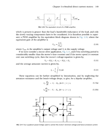
If we now consider a motor-drive application, Fig. 5.11, and if the switching period is
considerably smaller than the motor’s time constant and if the motor speed is constant
over one switching cycle, then the motor’s voltage equation is given by,
(5.11)
V m ¼ R a I a þ K e u m ¼ R a I a þ E m
and the average armature current is given by,
t f
1 Z
I a ¼ IðtÞdt (5.12)
t f
0
These equations can be further simplified by linearization, and by neglecting the
armature resistance and the brush-voltage drops, to give, for a bipolar amplifier,
di a
L a ¼ V s E m for 0 t t 1 (5.13a)
dt
di a
L a ¼ V s E m for t 1 t t f (5.13b)
dt
FIG. 5.11 Four quadrant power bridge used to control the motor’s terminal voltage and hence armature current.