
Page 152 - Electric Drives and Electromechanical Systems
P. 152
Chapter 5 Brushed direct-current motors 145
especially in ironless rotor and printed-circuit motors. Additional benefits include a
low deadband that eliminates crossover distortion and low radiated acoustic and
electromagnetic noise, due to the absence of switching devices.
5.3.2 Pulse width modulated servo drives
As noted earlier, when d.c., permanent-magnet, brushed motors are used in robotic or
machine-tool applications, the overall performance of the drive system will signifi-
cantly determine the accuracy and responseofeachmotionaxis. Thelineardrive
discussed are not suitable for the majority of applications due toexcessive power
dissipation.
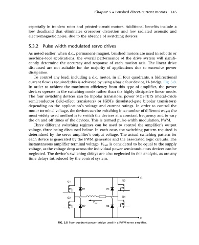
To control any load, including a d.c. motor, in all four quadrants, a bidirectional
current flow is required; this is achieved by using a basic four device, H-bridge, Fig. 5.8.
In order to achieve the maximum efficiency from this type of amplifier, the power
devices operate in the switching mode rather than the highly dissipative linear mode.
The four switching devices can be bipolar transistors, power MOSFETS (metal-oxide
semiconductor field-effect transistors) or IGBTs (insulated-gate bipolar transistors)
depending on the application’s voltage and current ratings. In order to control the
motor terminal voltage, the devices can be switching in a number of different ways; the
most widely used method is to switch the devices at a constant frequency and to vary
the on and off times of the devices. This is termed pulse-width modulation, PWM.
Three different switching regimes can be used to control the amplifier’s output
voltage, three being discussed below. In each case, the switching pattern required is
determined by the servo-amplifier’s output voltage. The actual switching pattern for
each device is generated by the PWM generator and the associated logic circuits. The
instantaneous amplifier terminal voltage, V out , is considered to be equal to the supply
voltage, as the voltage drop across the individual power semiconductors devices can be
neglected. The device’s switching delays are also neglected in this analysis, as are any
time delays introduced by the control system.
FIG. 5.8 Four quadrant power bridge used in a PWM servo amplifier.