
Page 150 - Electric Drives and Electromechanical Systems
P. 150
Chapter 5 Brushed direct-current motors 143
With the high number of brushes and commutator segments, there is minimal tor-
que ripple throughout the speed range.
The very low inductance of the motor ensures a long brush life due to the absence
of arcing at commutation this also allows high-speed, high-torque operation.
However it should be noted that the low induction could lead to excessive arma-
ture current form factors unless the drive is correctly matched to the drive.
5.3 Drives for d.c. brushed motors
The principle and the implementation of brushed, d.c., motor controllers is amongst the
simplest of all the motors considered in this book, with the motor speed being a direct
function of the voltage that is applied between the two motor terminals. The commu-
tation of the rotor current is undertaken by the mechanical arrangement of the
commutator and brushes. In servo applications the motor’s terminal voltage is normally
controlled by a linear or switching amplifier.
5.3.1 Linear amplifiers
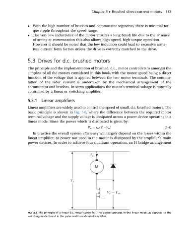
Linear amplifiers are widely used to control the speed of small, d.c. brushed motors. The
basic principle is shown in Fig. 5.6, where the difference between the required motor
terminal voltage and the supply voltage is dissipated across a power device operating in a
linear mode. Since the power which is dissipated is given by:
P m ¼ I m ðV s eV m Þ (5.4)
In practice the overall system efficiency will largely depend on the losses within the
linear amplifier, as power not used in the motor is dissipated by the amplifier’s main
power devices. In order to achieve four quadrant operation, an H-bridge arrangement
M
FIG. 5.6 The principle of a linear d.c. motor controller. The device operates in the linear mode, as opposed to the
switching mode found in the pulse width modulated amplifier.