
Page 153 - Electric Drives and Electromechanical Systems
P. 153
146 Electric Drives and Electromechanical Systems
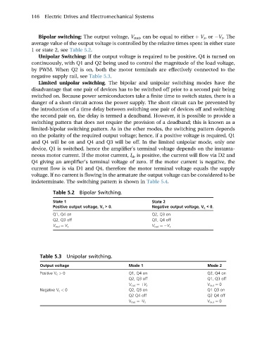
Bipolar switching: The output voltage, V out , can be equal to either þ V s ,or V s . The
average value of the output voltage is controlled by the relative times spent in either state
1 or state 2, see Table 5.2.
Unipolar Switching: If the output voltage is required to be positive, Q4 is turned on
continuously, with Q1 and Q2 being used to control the magnitude of the load voltage,
by PWM. When Q2 is on, both the motor terminals are effectively connected to the
negative supply rail, see Table 5.3.
Limited unipolar switching. The bipolar and unipolar switching modes have the
disadvantage that one pair of devices has to be switched off prior to a second pair being
switched on. Because power semiconductors take a finite time to switch states, there is a
danger of a short circuit across the power supply. The short circuit can be prevented by
the introduction of a time delay between switching one pair of devices off and switching
the second pair on, the delay is termed a deadband. However, it is possible to provide a
switching pattern that does not require the provision of a deadband; this is known as a
limited-bipolar switching pattern. As in the other modes, the switching pattern depends
on the polarity of the required output voltage; hence, if a positive voltage is required, Q1
and Q4 will be on and Q4 and Q3 will be off. In the limited unipolar mode, only one
device, Q1 is switched, hence the amplifier’s terminal voltage depends on the instanta-
neous motor current. If the motor current, I a , is positive, the current will flow via D2 and
Q4 giving an amplifier’s terminal voltage of zero. If the motor current is negative, the
current flow is via D1 and Q4, therefore the motor terminal voltage equals the supply
voltage. If no current is flowing in the armature the output voltage can be considered to be
indeterminate. The switching pattern is shown in Table 5.4.
Table 5.2 Bipolar Switching.
State 1 State 2
Positive output voltage, V c > 0. Negative output voltage, V c < 0.
Q1, Q4 on Q2, Q3 on
Q2, Q3 off Q1, Q4 off
V out ¼ V s V out ¼ V s
Table 5.3 Unipolar switching.
Output voltage Mode 1 Mode 2
Positive V c > 0 Q1, Q4 on Q2, Q4 on
Q2, Q3 off Q1, Q3 off
V out ¼þV s V out ¼ 0
Negative V c < 0 Q2, Q3 on Q1 Q3 on
Q2 Q4 off Q2 Q4 off
V out ¼ -V s V out ¼ 0