
Page 154 - Electric Drives and Electromechanical Systems
P. 154
Chapter 5 Brushed direct-current motors 147
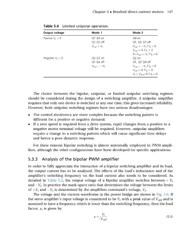
Table 5.4 Limited unipolar operation.
Output voltage Mode 1 Mode 2
Positive V c > 0 Q1 Q4 on Q4 on
Q2 Q3 off Q1, Q2 Q3 off
V out ¼ V c V out ¼ V s if I a < 0
V out ¼ 0if I a > 0
0<V out < V s if I a ¼ 0
Negative V c < 0 Q2 Q3 on Q2 on
Q1 Q4 off Q1, Q2 Q4 off
V out ¼ V c V out ¼ V s if I a > 0
V out ¼ 0if I a < 0
V s < V out <0if I a ¼ 0
The choice between the bipolar, unipolar, or limited unipolar switching regimes
should be considered during the design of a switching amplifier. A unipolar amplifier
requires that only one device is switched at any one time; this gives increased reliability.
However, both unipolar switching regimes have two serious disadvantages:
The control electronics are more complex because the switching pattern is
different for a positive or negative demand.
If a zero speed is required from a drive system, rapid changes from a positive to a
negative motor terminal voltage will be required. However, unipolar amplifiers
require a change to a switching pattern which will cause significant time delays
and hence a poor dynamic response.
For these reasons bipolar switching is almost universally employed in PWM ampli-
fiers, although the other configurations have been developed for specific applications.
5.3.3 Analysis of the bipolar PWM amplifier
In order to fully appreciate the interaction of a bipolar switching amplifier and its load,
the output current has to be analysed. The effects of the load’s inductance and of the
amplifier’s switching frequency on the load current also needs to be considered. As
detailed in Table 5.2, the output voltage of a bipolar amplifier switches between þ V s
and V s . In practice the mark-space ratio that determines the voltage between the limits
of þV s and V s is determined by the amplifiers command’s voltage, V c .
The voltage and the current waveforms in the power bridge are shown in Fig. 5.9.If
the servo amplifier’s input voltage is considered to be V c with a peak value of V cpk and is
assumed to have a frequency which is lower than the switching frequency, then the load
factor, r, is given by
V c
r ¼ (5.5)
jV cpk j