
Page 160 - Electric Drives and Electromechanical Systems
P. 160
Chapter 5 Brushed direct-current motors 153
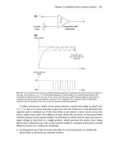
FIG. 5.13 The principle of the current-controlled hysteresis approach to generate the device switching signals for
the logic circuit shown in Fig. 5.16. The switching frequency is uncontrolled as it is directly determined by the
comparator’s hysteresis and the rise time of the current. (A) The pulse width modulated signal is generated by
comparing the actual load current against a reference. The comparator has a relatively high and adjustable
hysteresis. (B) The operation of the circuit and the resultant switching waveforms.
To allow satisfactory control of the power devices, a small-time delay is added (see
Fig. 5.15); this is to ensure that time is given for one set of devices to turn off before the
opposite pair is switched on. If this time delay is not added, a short circuit across the
power supply may result. The addition of logic allows the provision of directional limit
switches and an overall system enable. On activation of a limit-switch input, the motor’s
input voltage is restricted to a single polarity, which prevents the motor from being
driven into a physical stop. The overall system disable is normally activated by several
different sources (or conditions) including:
During power-up of the external controller, it is normal practice to disable the
motor-drive to prevent any transient motion.