
Page 174 - Electric Drives and Electromechanical Systems
P. 174
168 Electric Drives and Electromechanical Systems
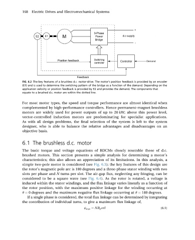
FIG. 6.2 The key features of a brushless d.c. motor-drive. The motor’s position feedback is provided by an encoder
(E1) and is used to determine the switching pattern of the bridge as a function of the demand. Depending on the
application velocity or position feedback is provided by E2 and provides the demand. The components that
equate to a brushed d.c. motor are within the dotted line.
For most motor types, the speed and torque performance are almost identical when
complemented by high-performance controllers. Hence permanent-magnet brushless
motors are widely used for power outputs of up to 20 kW; above this power level,
vector-controlled induction motors are predominating for specialist applications.
As with all design problems, the final selection of the system is left to the system
designer, who is able to balance the relative advantages and disadvantages on an
objective basis.
6.1 The brushless d.c. motor
The basic torque and voltage equations of BDCMs closely resemble those of d.c.
brushed motors. This section presents a simple analysis for determining a motor’s
characteristics; this also allows an appreciation of its limitations. In this analysis, a
simple two-pole motor is considered (see Fig. 6.3); the key features of this design are
the rotor’s magnetic pole arc is 180 degrees and a three-phase stator winding with two
slots per phase and N turns per slot. The air-gap flux, neglecting any fringing, can be
considered to be a square wave (see Fig. 6.4). As the rotor is rotated, a voltage is
induced within the stator windings, and the flux linkage varies linearly as a function of
the rotor position, with the maximum positive linkage for the winding occurring at
q ¼ 0 degrees and the maximum negative flux linkage occurring at q ¼ 180 degrees.
If a single phase is considered, the total flux linkage can be determined by integrating
the contribution of individual turns, to give a maximum flux linkage of,
j max ¼ NB g prl (6.1)