
Page 22 - Electric Drives and Electromechanical Systems
P. 22
14 Electric Drives and Electromechanical Systems
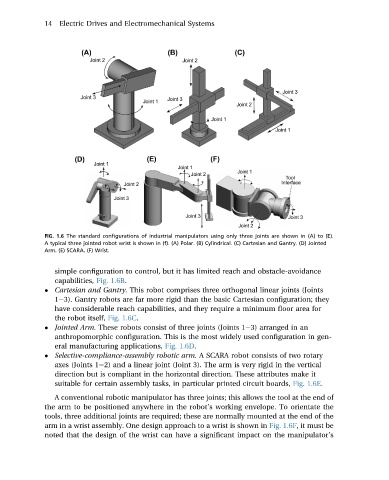
FIG. 1.6 The standard configurations of industrial manipulators using only three joints are shown in (A) to (E).
A typical three jointed robot wrist is shown in (f). (A) Polar. (B) Cylindrical. (C) Cartesian and Gantry. (D) Jointed
Arm. (E) SCARA. (F) Wrist.
simple configuration to control, but it has limited reach and obstacle-avoidance
capabilities, Fig. 1.6B.
Cartesian and Gantry. This robot comprises three orthogonal linear joints (Joints
1e3). Gantry robots are far more rigid than the basic Cartesian configuration; they
have considerable reach capabilities, and they require a minimum floor area for
the robot itself, Fig. 1.6C.
Jointed Arm. These robots consist of three joints (Joints 1e3) arranged in an
anthropomorphic configuration. This is the most widely used configuration in gen-
eral manufacturing applications, Fig. 1.6D.
Selective-compliance-assembly robotic arm. A SCARA robot consists of two rotary
axes (Joints 1e2) and a linear joint (Joint 3). The arm is very rigid in the vertical
direction but is compliant in the horizontal direction. These attributes make it
suitable for certain assembly tasks, in particular printed circuit boards, Fig. 1.6E.
A conventional robotic manipulator has three joints; this allows the tool at the end of
the arm to be positioned anywhere in the robot’s working envelope. To orientate the
tools, three additional joints are required; these are normally mounted at the end of the
arm in a wrist assembly. One design approach to a wrist is shown in Fig. 1.6F, it must be
noted that the design of the wrist can have a significant impact on the manipulator’s