
Page 25 - Electric Drives and Electromechanical Systems
P. 25
Chapter 1 Electromechanical systems 17
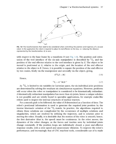
FIG. 1.8 The transformations that need to be considered when controlling the position and trajectory of a six-axis
robot. In this application the robot is required to place its end effector on the box, i.e. reducing the distance
represented by the transformation, B, to zero.
with respect to the base frame by a transform O (see Fig. 1.8). The position and orien-
0
tation of the tool interface of the six-axis manipulator is described by T 6 , and the
position of the end effector relative to the tool interface is given by E. The object to be
moved is positioned at G, relative to the origin, and the location of the end effector
relative to the object is B. Hence, it is possible to equate the position of the end effector
by two routes, firstly via the manipulator and secondly via the object, giving,
0
O T 6 E ¼ BG (1.6)
Hence,
0 T 6 ¼ O BGE 1 (1.7)
1
0
As T 6 , is limited to six variables in Cartesian space, the six individual joint positions
are determined by solving the resultant six simultaneous equations. However, problems
will occur when the robot or manipulator is considered to be kinematically redundant.
A kinematically redundant manipulator has more than six joints, hence a unique solution
is not possible and are widely found in specialist applications, for example snake-like
robots used to inspect the internal structures of nuclear reactors.
For a smooth path to be followed, the value of B determined as a function of time. The
robot’s positional information is used to generate the required joint position by the
0
inverse kinematic solution of the T 6 matrix. In practice, the algorithms required to
obtain these solutions are complicated by the occurrence of multiple solutions and
singularities, which are resolved by defining the trajectory, and is solution prior to
moving the robot. Usually, it is desirable that the motion of the robot is smooth; hence,
the first derivative (that is, the speed) must be continuous. As the robot moves, the
dynamics of the robot changes, as the forces and inertias seen by individual joints
change constantly. If the position loops are individually closed, a poor end-effector
response results, with a slow speed and unnecessary vibration. To improve the robot’s
performance, and increasingly that of CNC machine tools, considerable use of is made