
Page 32 - Electric Drives and Electromechanical Systems
P. 32
24 Electric Drives and Electromechanical Systems
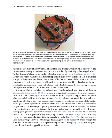
FIG. 1.12 A swarm robot measuring 100 mm 100 mm based on a single PCB board design, using an ARM Cortex-
M0 as the main controller. The robot has configurable analogue and digital subsystem which together with the
capability for I2C communication provides facilities for reconfiguration and expansion. Eight infra red (IR) LEDs
and four IR photodiodes are used detect objects to avoid as well as providing low level communication to other
swarm robots. In addition the robot is fitted with a ground facing colour sensor, accelerometer and
magnetometer.
mimic the structure and movement of humans and animals. Of particular interest to the
research community is the construction and control of dynamically stable legged robots.
In the design of these systems the following constraints exist (Robinson et al., 1999).
Firstly, the robot must be self-supporting, which puts severe limits on the force/mass
and power/mass ratio of the actuators. Secondly, the actuators of the robot must not be
damaged during impact steps or falls and must maintain stability following an impact.
Finally, the actuators may need to be force controllable because the in some approaches
the algorithms used for robot locomotion are force based.
A large number of walking robots have been developed with two, four or six legs, as
discussed by Zhou and Bi (2012) for a variety of applications ranging from pure research
through to load carrying for military or humanitarian logistics requirements in areas
where wheeled vehicles could not be used. Fig. 1.13 shows two possible approaches to
the design of a leg. One of two possible approaches are possible dependant of the design
of the joints that replicate the motion of the hip. The placement of the two coincident
hip joints has the advantage of placing the respective actuators on or close to the vehicle
body, so that their mass is not carried by the leg during motion. In addition, the design of
the hip joint provides optimum workspace and simplifies the kinematics. There are two
variations of this approach to leg design leg: mammal or insect inspiration. In the leg
based on a mammal, the knee joint is placed under the hip, Fig. 1.13A, this approach is
used in either biped robots or four legged running robots. In the insect-based design, the
knee joint is located laterally or at a position higher than the hip, Fig. 1.13B, this design to
typically used in six-legged insect-based robots.