
Page 35 - Electric Drives and Electromechanical Systems
P. 35
Chapter 1 Electromechanical systems 27
1.5 Aerospace applications
As with automotive applications, the aerospace industry is faced with challenge of
reducing operating costs, particularly fuel, and reducing environmental impact. In
addressing this challenge, designers are increasingly turning to the concept of the more-
electric-aircraft and the all-electric-aircraft. In this approach systems are replaced with
an electrically powered equivalent. While this will increase the aircraft’s electrical power
requirements, there is an overall saving in weight and increase in efficiency (Jones, 2002).
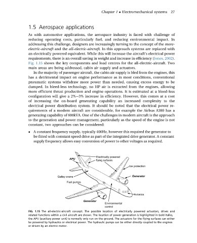
Fig. 1.15 shows the key components and load centres for the all-electric-aircraft. Two
main areas are being addressed, cabin air supply and actuators.
In the majority of passenger aircraft, the cabin air supply is bled from the engines, this
has a detrimental impact on engine performance as in most conditions, conventional
pneumatic systems withdraw more power than needed, causing excess energy to be
dumped. In bleed-less technology, no HP air is extracted from the engines, allowing
more efficient thrust production and engine operations. It is estimated at a bleed-less
configuration will give a 2%e3% increase in efficiency. However, this comes at a cost
of increasing the on-board generating capability an increased complexity to the
electrical power distribution system. It should be noted that the electrical power re-
quirements of a modern aircraft are considerable, for example the Airbus A380 has a
generating capability of 600kVA. One of the challenges in modern aircraft is the approach
to the generation and power management, particularly as the speed of the engine is not
constant, two approaches can be considered:
A constant frequency supply, typically 400Hz, however this required the generator to
be fitted with constant speed drive as part of the integrated drive generator. A constant
supply frequency allows easy conversion of power to other voltages as required.
FIG. 1.15 The all-electric-aircraft concept. The possible location of electrically powered actuators, drives and
related functions within a civil aircraft are shown. The location of power generation is highlighted in bold italics,
the APU (auxiliary power unit) is normally only run on the ground. The actuators for the flying surfaces can either
be powered by hydraulics or electrical power. The hydraulic pumps can be either directly coupled to the engines
or driven by an electric motor.