
Page 38 - Electric Drives and Electromechanical Systems
P. 38
30 Electric Drives and Electromechanical Systems
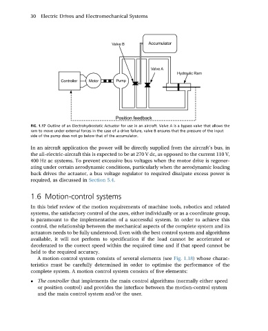
FIG. 1.17 Outline of an Electrohydrostatic Actuator for use in an aircraft. Valve A is a bypass valve that allows the
ram to move under external forces in the case of a drive failure, valve B ensures that the pressure of the input
side of the pump does not go below that of the accumulator.
In an aircraft application the power will be directly supplied from the aircraft’s bus, in
the all-electric-aircraft this is expected to be at 270 V dc, as opposed to the current 110 V,
400 Hz ac systems. To prevent excessive bus voltages when the motor drive is regener-
ating under certain aerodynamic conditions, particularly when the aerodynamic loading
back drives the actuator, a bus voltage regulator to required dissipate excess power is
required, as discussed in Section 5.4.
1.6 Motion-control systems
In this brief review of the motion requirements of machine tools, robotics and related
systems, the satisfactory control of the axes, either individually or as a coordinate group,
is paramount to the implementation of a successful system. In order to achieve this
control, the relationship between the mechanical aspects of the complete system and its
actuators needs to be fully understood. Even with the best control system and algorithms
available, it will not perform to specification if the load cannot be accelerated or
decelerated to the correct speed within the required time and if that speed cannot be
held to the required accuracy.
A motion-control system consists of several elements (see Fig. 1.18) whose charac-
teristics must be carefully determined in order to optimise the performance of the
complete system. A motion control system consists of five elements:
The controller that implements the main control algorithms (normally either speed
or position control) and provides the interface between the motion-control system
and the main control system and/or the user.