
Page 37 - Electric Drives and Electromechanical Systems
P. 37
Chapter 1 Electromechanical systems 29
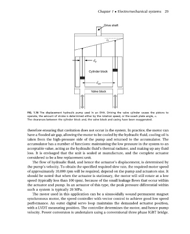
FIG. 1.16 The displacement hydraulic pump used in an EHA. Driving the valve cylinder causes the pistons to
operate, the amount of stroke is determined either by the rotation speed, or the swash plate angle, a.
The clearances between the cylinder block and, the valve block and casing have been exaggerated.
therefore ensuring that cavitation does not occur in the system. In practice, the motor can
have a flooded air gap, allowing the motor to be cooled by the hydraulic fluid, cooling oil is
taken from the high-pressure side of the pump and returned to the accumulator. The
accumulator has a number of functions: maintaining the low pressure in the system to an
acceptable value, acting as the hydraulic fluid’s thermal radiator, and making up any fluid
loss. It is envisaged that the unit is sealed at manufacture, and the complete actuator
considered to be a line replacement unit.
The flow of hydraulic fluid, and hence the actuator’s displacement, is determined by
the pump’s velocity. To obtain the specified required slew rate, the required motor speed
of approximately 10,000 rpm will be required, depend on the pump and actuators size. It
should be noted that when the actuator is stationary, the motor will still rotate at a low
speed (typically less than 100 rpm), because of the small leakage flows that occur within
the actuator and pump. In an actuator of this type, the peak pressure differential within
such a system is typically 20 MPa.
The motor used in this application can be a sinusoidally wound permanent magnet
synchronous motor, the speed controller with vector control to achieve good low speed
performance. An outer digital servo loop maintains the demanded actuator position,
with a LVDT measuring position. The controller determines the motor, and hence pump
velocity. Power conversion is undertaken using a conventional three phase IGBT bridge.