
Page 109 - Electric Machinery Fundamentals
P. 109
TRANSfORMERS 85
This net magnetomotive force must produce the net flux in the core, so the net
magnetomotive force must be equal to
IS'", = Npip - !'sis = ¢ 2h I (2-32)
where CJt is the reluctance of the transformer core. Because the reluctance of a well-
designed transformer core is very small (nearly zero) until the core is saturated, the
relationship between the primary and secondary currents is approximately
8"F net = Npip - Nsis = 0 (2- 33)
as long as the core is unsaturated. Therefore,
I Npip ~ Nsis I (2- 34)
i.e _ Ns = 1
or is - Np a (2-35)
(
It is the fact that the magnetomotive force in the core is nearly zero which gives
the dot convention the meaning in Section 2.3. In order for the magnetornotive
force to be nearly zero, current must flow into one dotted end and out of the other
dotted elld. The voltages must be built up in the same way with respect to the dots
on each winding in order to drive the currents in the direction required. (The po-
larity of the voltages can also be determined by Lenz's law if the construction of
the transformer coils is visible.)
What assumptions are required to convert a real transformer into the ideal
transformer described previously? They are as follows:
1. The core must have no hysteresis or eddy currents.
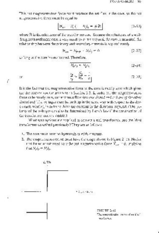
2. The magnetization curve must have the shape shown in Figure 2-15. Notice
that for an unsaturated core the net magnetomotive force 2Fnet :::; 0, implying
that Npip ::= Nsi .
s
0/. Wb
-------+-------STi, A· turns
(
FIGURE 2-15
The magnetization curve of an ideal
transformer.