
Page 112 - Electric Machinery Fundamentals
P. 112
aV,
(aJ
Rp , Xp
~ ) ~ R j X,. 1. 1 ,
-;?
+ AAA A ASA rvvv-. +
;VV
VVV
, j I
R, < ~ ,Xm
Vp J- V. I ,
a ;;2 ~ > a 2
j
(bJ
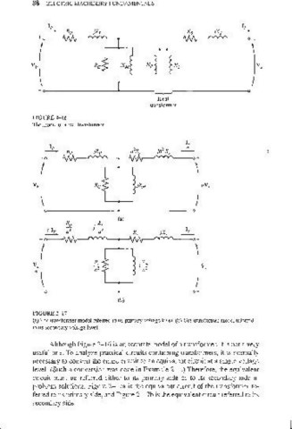
FIGURE 2- 17
(a) TIle Iransfonner model referred to its primary voltage level. (b) The transformer model referred
to it'> secondary volLagc level.
Although Figure 2-16 is an accurate model of a transformer, it is not a very
useful one. To analyze practical circuits containing transformers, it is normally
necessary to convert the entire circuit to an equivalent circuit at a single voltage
level. (Such a conversion was done in Example 2- 1.) Therefore, the equivalent
circuit must be refelTed either to its primary side or to its secondary side in
problem solutions. Figure 2-17a is the equivalent circuit of the transformer re-
fen'ed to its primary side, and Figure 2-17b is the equivalent circuit referred to its
secondary side.