
Page 116 - Electric Machinery Fundamentals
P. 116
Y2 EL ECTRIC MACHINERY FUNDAM EN'fALS
tt
,_W=a"m=et~er~, ip (/)
+ • •
Transformer
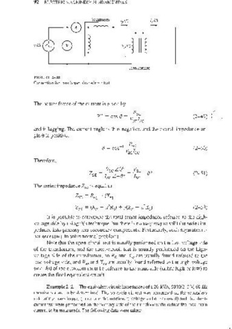
FIGURE 2-20
Connection for transformer shOtt-circuit test.
The power factor of the current is given by
Fsc
PF ~ cos e ~-- (2-49) (
Vsc1sc
and is lagging. The current angle is thus negative, and the overall impedance an-
gle e is positive:
(2-50)
Therefore,
c
Vsc LO
ZSE ~ I / _ "" (2- 51)
sc L.. (J
The series impedance ZSE is equal to
2SE ~ Req + iX,q
(2-52)
It is possible to determine the total series impedance referred to the high-
voltage side by using this technique, but there is no easy way to split the series im-
pedance into primary and secondary components. Fortunately, such separation is
not necessary to solve normal problems.
Note that the open-circuit test is usually performed on the low-voltage side
of the transformer, and the short-circuit test is usually performed on the high-
voltage side of the transformer, so Rc and X are usually found referred to the
M
low-voltage side, and R eq and X eq are usually found referred to the high-voltage
side. All of the elements must be referred to the same side (either high or low) to
create the final equivalent circuit.
Example 2-2. The equivalent circuit impedances of a 20-kVA, 8000/240 V, 60-Hz
transformer are to be determined. The open-circuit test was performed on the secondary
side of the transformer (to reduce the maximum voltage to be measured) and the short-
circuit test were performed on the primary side of tbe transformer (to reduce the maximum
current to be measured). The following data were taken: