
Page 118 - Electric Machinery Fundamentals
P. 118
94 ELECTRIC MACHINERY FUNDAMENTALS
I,
Ip Roq jX cq ~
AAA ,
+ V ~ +
I j {8 /n jl92n
IJr+e J pm
jX
Vp ~ ~ R, m aV,
< j38.4 kn
159 kn
\~--_~I----------~
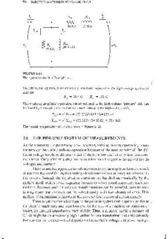
FIGURE 2-21
The equivalent circuit of Example 2-2.
(
Therefore, the equivalent resistance and reactance referred to the high-voltage (primary)
side are
Xeq = 1920
The resulting simplified equivalent circuit refelTed to the high-voltage (primary) side can
be found by converting the excitation branch values to the high-voltage side.
2
Re,p ~ a Res ~ (33.333)' (1 44 D)~ 1 59 kD
X"J' ~ a' X M • S ~ (33.333)' (34.63 D) ~ 38.4 kD
The resulting equivalent circuit is shown in Figure 2- 21.
2.6 THE PER-UNIT SYSTEM OF MEASUREMENTS
As the relatively simple Example 2-1 showed, solving circuits containing trans-
formers can be quite a tedious operation because of the need to refer all the dif-
ferent voltage levels on different sides of the transformers in the system to a com-
mon level. Only after this step has been taken can the system be solved for its
voltages and currents.
There is another approach to solving circuits containing transformers which
eliminates the need for explicit voltage-level conversions at every transformer in
the system. Instead, the required conversions are handled automatically by the
method itself, without ever requiring the user to worry about impedance transfor-
mations. Because such impedance transformations can be avoided, circuits con-
taining many transformers can be solved easily with less chance of error. This
method of calculation is known as the per-unit (pu) system of measurements.
There is yet another advantage to the per-unit system that is quite significant
for electric machinery and transformers. As the size of a machine or transformer
varies, its internal impedances vary widely. Thus, a primary circuit reactance of
0.1 n might be an atrociously high number for one transformer and a ridiculously
low number for another-it all depends on the device's voltage and power ratings.