
Page 123 - Electric Machinery Fundamentals
P. 123
TRANSFORMERS 99
of different sizes, transformer impedances are normal1y given in per-unit or as a
percentage on the transformer's nameplate (see Figure 2-45, later in this chapter).
The same idea applies to synchronous and induction machines as well: Their
per-unit impedances fall within relatively narrow ranges over quite large size ranges.
If more than one machine and one transformer are included in a single
power system, the system base voltage and power may be chosen arbitrarily, but
the entire system must have the same base. One common procedure is to choose
the system base quantities to be equal to the base of the largest component in the
system. Per-unit values given to another base can be converted to the new base by
converting them to their actual values (volts, amperes, ohms, etc.) as an lll-
between step. Alternatively, they can be converted directly by the equations
(P, Q, S)pu on base 2 = (P, Q, S)pu on base l~base I (2-58)
base 2
( v.: pu 0 11 base 2 = v.: pu on base 1 -~- (2-59)
Vbase 1
bare 2
(Vb,,, [)2(Sb'''' 2)
(R, X, ZJp" 0" b,,, 2 = (R, X, ZJp" 0" b,,, [ (~ )2(S ) (2-60)
base 2 base 1
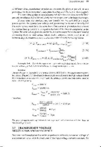
Example 2-4. Sketch the approximate per-unit equivalent circuit for the trans-
fonner in Example 2- 2. Use the transformer's ratings as the system base.
Solution
The transformer in Example 2-2 is rated at 20 kVA, 80001240 V. The approximate equiva-
lent circuit (Figure 2- 2 I) developed in the example was referred to the high-vohage side of
the transformer, so to converL it to per-unit, the primary circuit base impedance must be
found. On the primary,
V base I = 8000 V
Sbase I = 20,000 VA
Z _ (Vb,,, ,)2 _ (8000 VJ'
3200 fl
bnse I - Sbase I - 20,000 V A
Therefore,
38.4 + j l92 fl .
ZSE.P" = 3200 fl = 0.01 2 + jO.06 pu
159 kfl
Rc.P" = 3200 fl = 49.7 pu
38.4 kfl
ZM.P" = 3200 fl = 12 pu
The per-unit approximme equivalent circuit, expressed to the transformer's own base, is
shown in Figure 2- 25.
2.7 TRANSFORMER VOLTAGE
REGULATION AND EFFICIENCY
Because a real transformer has series impedances within it, the output voltage of
a transformer varies with the load even if the input voltage remains constant. To