
Page 122 - Electric Machinery Fundamentals
P. 122
98 ELECTRIC MACHINERY FUNDAMENTALS
(
(a) (b)
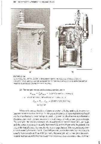
FIGURE 2- 24
(a) A typical 13.2-kV to 1201240-V distribution transfonner. (Courtesy afGeneral Electric
Company.) (b) A cutaway view of the distribution transformer showing the shell-form transformer
inside it. (Courtesy a/General Electric Company.)
Cd) The per-unit power lost in the transmission line is
P1ine,pu = !~lIR1ine.pu = (0.569)2(0.0087) = 0.00282
and the actual power lost in the transmission line is
~ine = Rine,pu Sbase = (0.00282)( 1 0,000 V A)
~ 28.2 W
When only one device (transformer or motor) is being analyzed, its own rat-
ings are usually used as the base for the per-unit system. If a per-unit system based
on the transformer's own ratings is used, a power or distribution transformer's
characteristics will not vary much over a wide range of voltage and power ratings.
For example, the series resistance of a transformer is usually about 0.01 per unit,
and the series reactance is usually between 0.02 and 0.10 per unit. In general, the
larger the transformer, the smaller the series impedances. The magnetizing reac-
tance is usually between about 10 and 40 per unit, while the core-loss resistance is
usually between about 50 and 200 per unit. Because per-unit values provide a con-
venient and meaningful way to compare transformer characteristics when they are