
Page 129 - Electrical Equipment Handbook _ Troubleshooting and Maintenance
P. 129
INDUCTION MOTORS
6.18 CHAPTER SIX
A starting code letter has been established to estimate the rotor current when the motor
is starting. This code letter sets the limit on the magnitude of the current that the motor can
draw at starting conditions. These limits are given in terms of the starting apparent power
of the motor as a function of its horsepower rating. Table 6.1 shows the starting kVA per
horsepower for each code letter. The NEMA code letters indicate the starting kilovoltam-
peres per horsepower of rating for a motor. Each code letter extends up to, but does not
include, the lower bound of the next higher class.
The starting current of an induction motor can be determined by
(rated horsepower)(code letter factor)
I
L
3(rated voltage)
The starting current can be reduced if necessary, by a starting circuit. However, this results
in reduction of the starting torque of the motor. The starting current of an induction motor
can be reduced by inserting extra inductors or resistors in the power line during starting
conditions. Alternatively, the terminal voltage of the motor can be reduced during starting
by using an autotransformer to step it down.
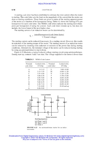
Figure 6.22 illustrates a typical reduced-voltage starting circuit using autotransformers.
During start-up, contacts 1 and 3 are shut. The voltage supplied to the motor is lower than
TABLE 6.1 NEMA Code Letters
Nominal Locked rotor, Nominal Locked rotor,
code letter kVA/hp code letter kVA/hp
A 0–3.15 L 9.00–10.00
B 3.15–3.55 M 10.00–11.20
C 3.55–4.00 N 11.20–12.50
D 4.00–4.50 P 12.50–14.00
E 4.50–5.00 R 14.00–16.00
F 5.00–5.60 S 16.00–18.00
G 5.60–6.30 T 18.00–20.00
H 6.30–7.10 U 20.00–22.40
J 7.10–8.00 V 22.40 and up
K 8.00–9.00
FIGURE 6.22 An autotransformer starter for an induc-
tion motor.
Downloaded from Digital Engineering Library @ McGraw-Hill (www.digitalengineeringlibrary.com)
Copyright © 2004 The McGraw-Hill Companies. All rights reserved.
Any use is subject to the Terms of Use as given at the website.