
Page 125 - Electrical Equipment Handbook _ Troubleshooting and Maintenance
P. 125
INDUCTION MOTORS
6.14 CHAPTER SIX
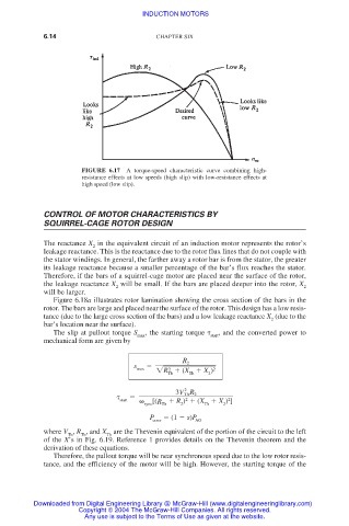
FIGURE 6.17 A torque-speed characteristic curve combining high-
resistance effects at low speeds (high slip) with low-resistance effects at
high speed (low slip).
CONTROL OF MOTOR CHARACTERISTICS BY
SQUIRREL-CAGE ROTOR DESIGN
The reactance X in the equivalent circuit of an induction motor represents the rotor’s
2
leakage reactance. This is the reactance due to the rotor flux lines that do not couple with
the stator windings. In general, the farther away a rotor bar is from the stator, the greater
its leakage reactance because a smaller percentage of the bar’s flux reaches the stator.
Therefore, if the bars of a squirrel-cage motor are placed near the surface of the rotor,
the leakage reactance X will be small. If the bars are placed deeper into the rotor, X
2 2
will be larger.
Figure 6.18a illustrates rotor lamination showing the cross section of the bars in the
rotor. The bars are large and placed near the surface of the rotor. This design has a low resis-
tance (due to the large cross section of the bars) and a low leakage reactance X (due to the
2
bar’s location near the surface).
The slip at pullout torque S , the starting torque , and the converted power to
max start
mechanical form are given by
R 2
s
max R (X X ) 2
2
Th Th 2
2
3V Th R 2
2
2
[(
start sync R Th R ) (X X ) ]
2
Th
2
P (1 s)P
conv AG
where V , R , and X are the Thevenin equivalent of the portion of the circuit to the left
Th Th Th
of the X’s in Fig. 6.19. Reference 1 provides details on the Thevenin theorem and the
derivation of these equations.
Therefore, the pullout torque will be near synchronous speed due to the low rotor resis-
tance, and the efficiency of the motor will be high. However, the starting torque of the
Downloaded from Digital Engineering Library @ McGraw-Hill (www.digitalengineeringlibrary.com)
Copyright © 2004 The McGraw-Hill Companies. All rights reserved.
Any use is subject to the Terms of Use as given at the website.