
Page 121 - Electrical Equipment Handbook _ Troubleshooting and Maintenance
P. 121
INDUCTION MOTORS
6.10 CHAPTER SIX
FIGURE 6.11 The power flow diagram of an induction motor.
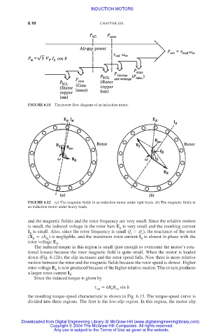
FIGURE 6.12 (a) The magnetic fields in an induction motor under light loads. (b) The magnetic fields in
an induction motor under heavy loads.
and the magnetic fields) and the rotor frequency are very small. Since the relative motion
is small, the induced voltage in the rotor bars E is very small and the resulting current
R
I is small. Also, since the rotor frequency is small (f sf ), the reactance of the rotor
R r e
(X sX ) is negligible, and the maximum rotor current I is almost in phase with the
R R 0 R
rotor voltage E .
R
The induced torque in this region is small (just enough to overcome the motor’s rota-
tional losses) because the rotor magnetic field is quite small. When the motor is loaded
down (Fig. 6.12b), the slip increases and the rotor speed falls. Now there is more relative
motion between the rotor and the magnetic fields because the rotor speed is slower. Higher
rotor voltage E is now produced because of the higher relative motion. This in turn produces
R
a larger rotor current I .
R
Since the induced torque is given by
ind kB B sin
R
net
the resulting torque-speed characteristic is shown in Fig. 6.13. The torque-speed curve is
divided into three regions. The first is the low-slip region. In this region, the motor slip
Downloaded from Digital Engineering Library @ McGraw-Hill (www.digitalengineeringlibrary.com)
Copyright © 2004 The McGraw-Hill Companies. All rights reserved.
Any use is subject to the Terms of Use as given at the website.