
Page 116 - Electrical Equipment Handbook _ Troubleshooting and Maintenance
P. 116
INDUCTION MOTORS
INDUCTION MOTORS 6.5
(a)
(b)
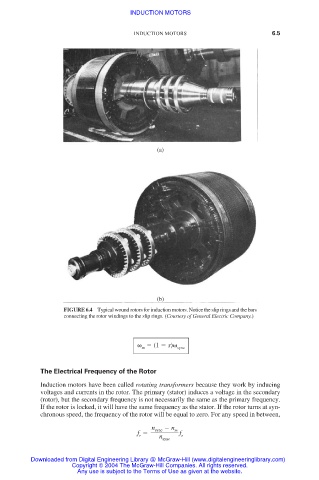
FIGURE 6.4 Typical wound rotors for induction motors. Notice the slip rings and the bars
connecting the rotor windings to the slip rings. (Courtesy of General Electric Company.)
(1 s) sync
m
The Electrical Frequency of the Rotor
Induction motors have been called rotating transformers because they work by inducing
voltages and currents in the rotor. The primary (stator) induces a voltage in the secondary
(rotor), but the secondary frequency is not necessarily the same as the primary frequency.
If the rotor is locked, it will have the same frequency as the stator. If the rotor turns at syn-
chronous speed, the frequency of the rotor will be equal to zero. For any speed in between,
n sync n
m
f f
r n sync e
Downloaded from Digital Engineering Library @ McGraw-Hill (www.digitalengineeringlibrary.com)
Copyright © 2004 The McGraw-Hill Companies. All rights reserved.
Any use is subject to the Terms of Use as given at the website.