
Page 117 - Electrical Equipment Handbook _ Troubleshooting and Maintenance
P. 117
INDUCTION MOTORS
6.6 CHAPTER SIX
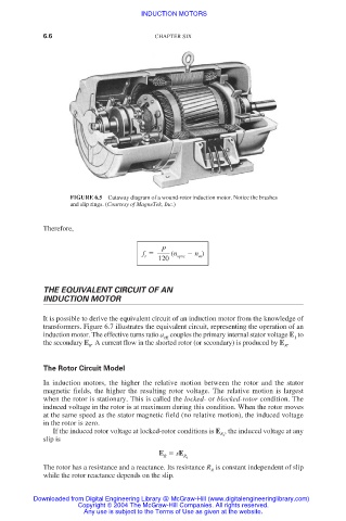
FIGURE 6.5 Cutaway diagram of a wound-rotor induction motor. Notice the brushes
and slip rings. (Courtesy of MagneTek, Inc.)
Therefore,
P
f (n n )
r sync m
120
THE EQUIVALENT CIRCUIT OF AN
INDUCTION MOTOR
It is possible to derive the equivalent circuit of an induction motor from the knowledge of
transformers. Figure 6.7 illustrates the equivalent circuit, representing the operation of an
induction motor. The effective turns ratio a couples the primary internal stator voltage E to
eff 1
the secondary E . A current flow in the shorted rotor (or secondary) is produced by E .
R R
The Rotor Circuit Model
In induction motors, the higher the relative motion between the rotor and the stator
magnetic fields, the higher the resulting rotor voltage. The relative motion is largest
when the rotor is stationary. This is called the locked- or blocked-rotor condition. The
induced voltage in the rotor is at maximum during this condition. When the rotor moves
at the same speed as the stator magnetic field (no relative motion), the induced voltage
in the rotor is zero.
If the induced rotor voltage at locked-rotor conditions is E , the induced voltage at any
R 0
slip is
E sE
R R 0
The rotor has a resistance and a reactance. Its resistance R is constant independent of slip
R
while the rotor reactance depends on the slip.
Downloaded from Digital Engineering Library @ McGraw-Hill (www.digitalengineeringlibrary.com)
Copyright © 2004 The McGraw-Hill Companies. All rights reserved.
Any use is subject to the Terms of Use as given at the website.