
Page 120 - Electrical Equipment Handbook _ Troubleshooting and Maintenance
P. 120
INDUCTION MOTORS
INDUCTION MOTORS 6.9
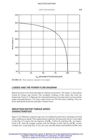
FIGURE 6.10 Rotor current as a function of rotor speed.
LOSSES AND THE POWER FLOW DIAGRAM
Induction motors have been described as rotating transformers. The input is a three-phase
system of voltages and currents. The secondary windings of the motor (the rotor) are
shorted out. Figure 6.11 illustrates the relationship between the input electric power and the
2
output mechanical power. The stator copper losses are I R in the stator windings. The core
losses include the hysteresis and eddy currents losses.
INDUCTION MOTOR TORQUE-SPEED
CHARACTERISTICS
Figure 6.12a illustrates a squirrel-cage rotor of an induction motor that is operating at no load
(near synchronous speed). The magnetization current I flowing in the motor’s equivalent
M
circuit (Fig. 6.7) creates the net magnetic field B . Current I and hence B are propor-
net M net
tional to E . Since E remains constant with the changes in load, then I and B remain
1 1 M net
constant also. At no load (Fig. 6.12a), the rotor slip (the relative motion between the rotor
Downloaded from Digital Engineering Library @ McGraw-Hill (www.digitalengineeringlibrary.com)
Copyright © 2004 The McGraw-Hill Companies. All rights reserved.
Any use is subject to the Terms of Use as given at the website.